Induction coil design can have a major impact on part quality, process efficiency, and manufacturing costs. How do you know if your coil design is best for your part and process? Here are some induction coil basics and five tips to optimize your design.
How Induction Heating Coils Work
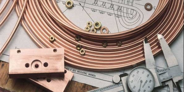
The induction coil determines how effectively and efficiently a workpiece is heated. Induction coils are water-cooled copper conductors made of tubing that is formed into the shape of the coil for the induction heating process. Induction heating coils do not themselves get hot as water flows through them.
>> Read our comprehensive guide to designing induction coils
Work coils range in complexity from a simple helical- or solenoid-wound coil (consisting of a number of turns of copper tube wound around a mandrel) to a coil that is precision machined from solid copper and then brazed.
Coils transfer energy from the induction heater power supply to the workpiece by generating an alternating electromagnetic field from the alternating current flowing in them. The coil’s alternating electromagnetic field (EMF) generates an induced current (eddy current) in the workpiece, which generates heat due to I Squared R losses (core losses).
The current in the workpiece is proportional to the coil’s EMF strength. This transfer of energy is known as the transformer effect or eddy current effect.
Transformers & Induction Coils
Because coils use the transformer effect, characteristics of transformers can be helpful in understanding coil design. The inductor is similar to a transformer primary, and the workpiece is equivalent to the transformer secondary (assumed to be a single turn).
There are two important features of transformers that impact coil design:
-
Efficiency of coupling between the windings is inversely proportional to the square of the distance between them
-
(Current in the primary of the transformer * # of primary turns) = (current in the secondary * # of secondary turns)
Five conditions to keep in mind
1. Higher flux density near the heating area means a higher current is generated in the part
The coil should be positioned as close to the part as possible with the largest possible number of magnetic flux lines intersecting the workpiece at the heating point. This allows for maximum energy transfer.
2. The greatest number of flux lines in a solenoid coil are toward the center of the coil
The flux lines are concentrated inside the coil, providing the maximum heating rate at that location.
3. The geometric center of the coil is a weak flux path
Flux is most concentrated closer to the coil turns themselves, and decreases with distance from the turns.
If a part were placed off center in a coil, the area closer to the coil turns would intersect a greater number of flux lines and thus be heated at a higher rate. The area of the part away from the copper coil experiences less coupling and would be heated at a lower rate.
This effect is more pronounced in high-frequency induction heating.
4. The magnetic center of the inductor is not necessarily the geometric center.
At the point where the leads and coil join, the magnetic field is weaker.
This effect is most pronounced in single-turn coils. As the number of coil turns increases and the flux from each turn is added to that from the previous turns, this condition becomes less important.
Due to the impracticality of always centering the part in the work coil, the part should be offset slightly toward this area in static heating applications. If possible, the part should be rotated to provide uniform exposure.
5. Coil must be designed to prevent cancellation of the magnetic field.
If opposite sides of the inductor are too close, the coil does not have sufficient inductance required for efficient heating. Putting a loop in the coil at the center will offset this effect. The coil will then heat a conducting material inserted in the opening.
Ambrell designs and manufactures coils for its power supplies, and even for non-Ambrell systems when provided with a drawing. Have questions about induction heating coil design?
Read our comprehensive guide to designing induction coils
or contact our experts for personal assistance.