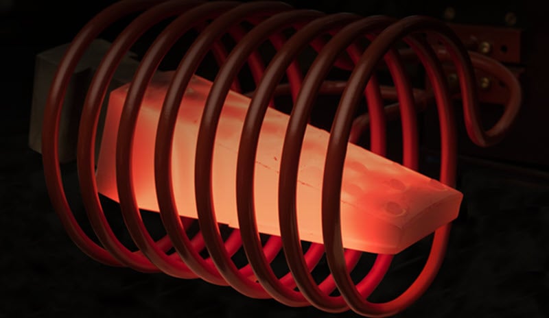
The type and design of the induction coil determines how effectively and efficiently a workpiece is heated. Work coils range in complexity from a simple helical- or solenoid-wound coil (consisting of a number of turns of copper tube wound around a mandrel) to a coil that is precision-machined from solid copper and brazed.
Read our Induction Coil Design PDF.
The helical solenoid coil is the most ubiquitous induction coil design. It provides a wide range of heating behaviors since the part or heating area is located within the coil, in the area of greatest magnetic flux. Flux lines in a solenoid coil are concentrated inside the coil, providing the maximum heating rate at that location.
6 Common Types of Solenoid Coils for Induction Heating Applications
1. Multi-turn helical coil
The helical (solenoid) is the most common and by far the most efficient coil. The design is relatively simple, since the number of turns defines the length of the heating pattern.
The workpiece can be stationary in this type of coil to provide a defined heating band in “single shot heating.” Or, the workpiece can be moved through the coil to heat a longer part with a highly uniform heating pattern called “scan heating.”
2. Multi-position helical coil
Multi-position coils are often used to produce more parts in a given time while allowing for the full heating process.
Any number of positions are possible but typically up to eight positions are practical. Parts can be heated simultaneously or can be indexed in and out of different positions, depending on the heating process required.
3. Pancake induction coil
Pancake induction coils are used when it’s necessary to heat the workpiece from only one side, or when it’s not possible to surround the part. Pancake coils can also be used to heat a small narrow band in the center of the part.
The pancake coil provides a wide range of heating behaviors since the flux from only one surface intersects with the workpiece.
4. Split helical coil
Single- or multiple-turn split helical coils are used when it’s not possible to access the target heating area using a helical coil.
Conducting through split coils
The faces of the hinged and fixed portions of the coil must have good surface-to-surface contact. These are typically faced with silver, or special alloys matched to provide good contact. Clamps are used to ensure closure during heating. High currents pass through this interface at high frequency, which means the life of the contact is generally limited.
Securing split coils
Split coils often require a means of locating the part in the coil to maintain proper coupling distance. Ceramic pins or buttons are frequently secured to the face of the inductor. These are subject to thermal shock during heating/quenching and should be designed for simple replacement.
Quenching through a split coil
Some applications will require the split-coil design to include the ability to quench through the face of the inductor.
Coolant for the coil chamber of the split inductor is carried by flexible hoses that bypass the hinge so that excessive heating does not occur in the movable section during the cycle. The quench chamber is fed by a separate hose arrangement.
The face of the quench chamber is closest to the work during heating, and carries most of the current. It must be sufficiently thick to avoid melting or distortion during the heating cycle.
5. Butterfly coils
Butterfly coils are ideal for creating an even heating pattern at the end of a bar or shaft.
Butterfly coils have two specially formed pancake coils. Center turns must be wound in the same direction so the current paths are additive. ONLY these center turns should couple directly with the part to produce the desired pattern.
The butterfly “wings” may be bent up to decouple their fields from the shaft, or may be coupled with the shaft itself.
6. Master work coils & inserts
Master coils and inserts are typically used for small batches where a single-turn coil can be used.
Master work coils provide a simple, rapid means of changing coil diameters or shapes to match a variety of parts. Master work coils typically consist of copper tubing that provides both an electrical connection to the power supply and a water-cooled contact surface for connection to a coil insert.
The copper tube is bent into the form of a single-turn coil and soldered to a copper band that conforms to the slope of the coil insert and is recessed.
Read about designing coil inserts in the full Induction Coil Design PDF.
Solenoid Coil Design Calculations
Coupling distance
Generally, distance increases with the diameter of the part, typical values being 0.75, 1.25, and 1.75 inches (19, 32 and 44 mm) or billet-stock diameters of approximately 1.5, 4 and 6 inches (38, 102, and 152 mm), respectively.
When the length of the coil exceeds 4-8x its diameter, uniform heating at high power densities becomes difficult. In these instances, single-turn or multiturn coils that scan the length of the workpiece are often preferable.
Coupling efficiency
Efficiency of coupling between the windings is inversely proportional to the square of distance between them.
Minimum tubing OD
Minimum outer diameter of copper tubing is 0.125 in (0.32 cm) to allow for water cooling.
Rotational speed
For most hardening operations, which are of short duration, rotational speeds producing AT LEAST 10 revolutions during the heating cycle should be used.
Current
(Current in the primary of the transformer * # of primary turns) = (current in the secondary * # of secondary turns)
Voltage loss
If the inductance of the coil (L2) is approximately ten times the total inductance of the leads (L1 plus L3) or greater, a maximum of 10% of the total voltage will be lost in the leads.
Any loss less than this can be considered nominal.
Want more information about designing solenoid coils for induction heating? Contact our team for personalized assistance with your product or application.
Our Coil Design Guide